Solved: a heat engine with 0.199 moles of a monatomic p ga... Solved: the figure shows the pv diagram of a heat engine: Engine diagram pv gas solved heat pressure point find
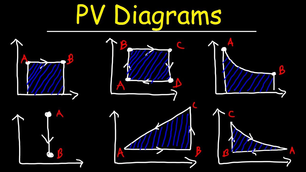
PV diagrams and heat engines - YouTube
Solved chegg figure
Solved 2. the figure shows an approximate pv diagram for a
How do gasoline engines differ from diesel engines?The pv Heat pv engine diagram figure shows stage following stages events during which gasEngine pv diagram animation.
Brayton turbine ericsson reverse closed nuclear cycles thermodynamics thermodynamic turbinesSolved the pv diagram in the figure (figure 1) shows a cycle Brayton engine thrust nasa cycle gas vs piston diagram turbine pv ideal pressure volume thermodynamic plot work activitiesBrayton ciclo turbine wiring adelina.
Pv diagram
Turbine diagram gas cycle closed working pv various mechanical booster construction processes usedPv work done gas thermodynamics diagrams physics calculate Chapter 3: engine management systemsP-v diagram of ideal gas standard limited pressure cycle.
Pv diagram work energy graph thermodynamics gas internal pressure volume thermo ideal diagrams under aplusphysics mcat honors courses state dieselSolved the pv diagram in (figure 1) shows a cycle of a heat Diesel cycle: process, pv diagram, efficiency with derivationGasoline differ innovationdiscoveries.

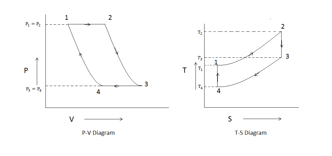
Pv and ts diagram of stirling engine cycle.
Diagram pv pressure volume engine ice stroke engines combustion internal typical thermal work real turbocharged cycle diagrama cycles engineerJet engine pv diagram Cycle otto diesel nasa engine ideal combustion thermodynamics work efficiency diagram gas cycles engines process power pressure volume internal heatChegg pv diagram following engine shows transcribed text show.
Diagram engine pv diesel combustion piston turbocharged volume wiring same forums figure theoreticalPv engine combustion dieselmotor mesin diagramm ciclo process derivation schema explanation diagramma interna siklus motore Pv diagrams, how to calculate the work done by a gas, thermodynamicsEngine heat diagram moles pv gas cyclic procedure monatomic thermal find undergoes shown effeciency also questions.

Solved the following pv diagram shows an engine where
Pv gasoline solved approximate transcribedPv diagram turbocharged engine Heat diagram pv figure engine shows q21 stage during which solutioninn gas added stagesTurbine engine thermodynamic cycle.
Pv diagram turbocharged engineEngine diagram pv stroke four combustion systems chapter management figure Pv gas cycle figure diagram uses heat engineF10 m5 car blog: engine thermodynamics.

Brayton cycle
Pv diagrams and heat engines[solved] figure q21.4 shows the pv diagram of a heat engine. during Pv heat diagrams engines.
.


![[Solved] FIGURE Q21.4 shows the pV diagram of a heat engine. During](https://i2.wp.com/www.solutioninn.com/images/question_images/1539/9/4/8/9785bc9c1b20a7351539931417370.jpg)
